The two main objectives of work package 3 within Seabat are: 1) the development of a modular and scalable hybrid battery system architecture for waterborne transport allowing storage capacities of over 1 MWh and 2) define the preliminary design of such a battery system at +-300kWh with a reduced cost compared to current state-of-the-art. The preliminary design of all the battery system components will be addressed within WP3, which later will be designed and developed in details in WP4 in order to be assembled as a battery system in WP5 and finally to be tested and validated in WP6.
The SEABAT topology that will be developed is selected based on the evaluations within T3.1, as discussed in our previous newsletter. The distributed converter topology, see figure 1, performs best on cost, volume, weight and total system losses. Either high power or high energy battery cells are used within the modules, that are combined in series into a string that consists out of the same type of modules to achieve the required DC-voltage. Different strings can be combined in parallel on system level to provide the overall power/capacity for the application. Each module has a build in low cost DC/DC converter in order to generate a stabilized output voltage.
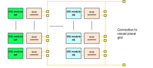
Figure 1 – distributed converter topology
ESS: energy storage system
HP: High power
HE: High Energy
This topology has been explained in detail by means of subdomains on electrical (FM), thermal (ABEE), mechanical (FHG-LBF), communication & control (FM), safety architecture (FHG-LBF) as well as requirements (FM), manufacturing & disassembly strategy (IKL) and cost reduction verification (FM).
All requirements and functionalities have been categorized to ensure that each sub domain knows the correct requirements, an overview on how the subdomains are connected and their interaction is developed. Each subdomain created a preliminary architecture that copes with these requirements.
All requirements and functionalities have been categorized to ensure that each sub domain knows the correct requirements, an overview on how the subdomains are connected and their interaction is developed. Each subdomain created a preliminary architecture that copes with these requirements.
Electrical: Cell selection and sizing of HE and HP battery modules was performed and a three level architecture was developed: Module – string – system taking into account the modularity and flexibility.
Thermal: The cooling method in a module is defined which is based on liquid cooling for the cells, and a first architecture on string and system level is proposed. On module level, the number and position of thermal sensors needs to be defined accordingly because it will define the sensing accuracy.
Mechanical: The mechanical architecture for a Lithium-Ion based battery system was defined in general and based on the requirements optimal design solution were suggested. An analysis was done to ensure a one size module that can be used for either HE or HP cells.
Communication & control architecture: A three level control architecture was proposed: module-string – pack that takes the interaction of the control system with other subsystems of electrical, thermal, safety and miscellaneous systems into account,
Safety architecture: The safety architecture was developed to mitigates risks and hazards of the battery system. The safety-relevant elements of the battery system were identified. For this purpose, a list of the components with their functions and malfunctions was compiled and assigned to the individual subtasks.
Manufacturing & disassembly strategy: This subtask provided guidelines and design criteria for the manufacturing of the SEABAT battery system based on: joining techniques, automatization methods for assembly and disassembly, manufacturing design recommendations and the evaluation of second life application.
Cost: The cost reduction while respecting the efficiency and safety aspects is considered during the development of each sub-architecture and documented. The cost calculation methodology for the entire battery system and some preliminary cost targets were identified.
Based on the architecture the preliminary design for a specific battery size was developed. Figure 2 provides a top level summary of the preliminary design.
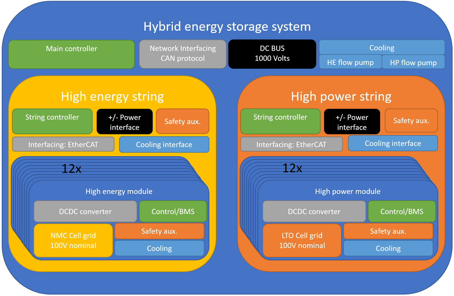
Figure 2 – Top level HESS preliminary design overview
There is a single instance of the HESS main controller and its peripherals. For this particular design, only a single instance for each string unit (the large yellow and orange blocks) exist, though multiple high energy or high power strings could be placed in parallel, depending on the desired energy capacity. Within each instance of a string, a number of string specific components exist, as well as the twelve in-series module units which generate the needed DC bus voltage that each string provides. Within each module, a number of module specific components exist. Because of modular design choices and cost, there is a large similarity between the modules for high energy and high power. The cells are selected in such a way that the same DCDC converter is used for both the HE and HP module.